
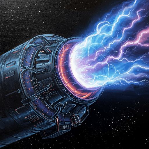
Experimenting in my Lab in Central Texas, here is an artist design of my working plasma motor. It would allow Astronauts to get to Mars in Two Weeks.

An American Plasma Rocket allowing for travel from Earth to Mars in Two Weeks!
But you can design your own-
Let’s design a simplified conceptual plasma rocket motor and explain its operation. Since I can’t create actual hardware, this will be a theoretical design.
Simplified Conceptual Plasma Rocket Motor Design:
- Plasma Generation Chamber: A cylindrical chamber made of a heat-resistant material like ceramic or a specialized alloy. This is where the plasma is created.
- Propellant Inlet: A small opening at one end of the chamber where the propellant (e.g., a noble gas like xenon or argon) is injected.
- Electrodes: Two electrodes, one at each end of the chamber. These could be ring-shaped or plate-shaped. They are connected to a high-voltage power supply.
- Magnetic Coils (optional but beneficial): Coils of wire wrapped around the chamber. When energized, they create a magnetic field that helps confine and direct the plasma.
- Nozzle: A shaped opening at the exhaust end of the chamber. This nozzle helps accelerate the plasma and direct the thrust.
How it Works:
- Propellant Injection: The propellant gas is injected into the plasma generation chamber.
- Plasma Creation: A high voltage is applied across the electrodes. This creates a powerful electric field within the chamber. The electric field ionizes the gas, stripping electrons from the atoms and creating a plasma – a superheated gas of charged particles (ions and electrons).
- Acceleration: The electric field exerts a force on the charged particles in the plasma. The ions, being positively charged, are accelerated towards the negatively charged electrode (the cathode). If magnetic coils are used, the magnetic field helps to focus and channel the plasma flow, increasing efficiency.
- Exhaust and Thrust: The accelerated plasma exits the chamber through the nozzle. The high-speed expulsion of this plasma creates thrust, propelling the rocket forward, according to Newton’s Third Law (for every action, there is an equal and opposite reaction).
Why this design (and plasma rockets in general) could be advantageous:
- High Specific Impulse: Specific impulse is a measure of how efficiently a rocket uses its propellant. Plasma rockets have the potential for very high specific impulse compared to chemical rockets. This means they can achieve more thrust from the same amount of propellant, or the same thrust from less propellant. This is crucial for long-duration space missions.
- Variable Thrust: The thrust of a plasma rocket can be adjusted by changing the power applied to the electrodes. This allows for fine control of the spacecraft’s acceleration.
- Potential for Advanced Propellants: While current plasma rockets often use noble gases, future designs might utilize more readily available propellants, or even potentially harvest propellants from other celestial bodies.
Why this design is simplified and the challenges:
- Complexity: Building a functional plasma rocket is incredibly complex. Maintaining the plasma, controlling the magnetic fields (if used), and ensuring the durability of the materials under extreme heat and radiation are significant engineering hurdles.
- Power Requirements: Plasma rockets require a substantial power source. For space applications, this likely means large solar arrays or potentially even nuclear reactors.
- Electrode Erosion: The high-energy plasma can erode the electrodes over time, limiting the lifespan of the engine.
In summary: While the concept of a plasma rocket is relatively simple, the actual implementation is a complex engineering challenge. However, the potential benefits of high specific impulse and variable thrust make plasma rockets a promising area of research for future space exploration. This simplified design helps to illustrate the fundamental principles behind how these engines work. Sources and related content
Mars in 30 days? Russia unveils prototype of plasma rocket engine – World Nuclear News
Magnetic Fusion Plasma Drive – arXiv
Our Engine – Ad Astra Rocket Company – Houston, US
How Plasma Rockets Work – Science | HowStuffWorks

Let’s design a simplified conceptual plasma rocket motor and explain its operation.
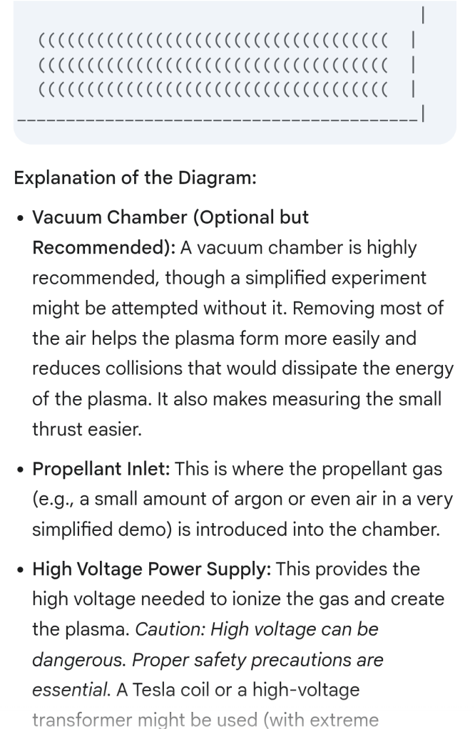
- High Voltage Power Supply: This provides the high voltage needed to ionize the gas and create the plasma. Caution: High voltage can be dangerous. Proper safety precautions are essential. A Tesla coil or a high-voltage transformer might be used (with extreme caution).
- Electrodes: Two electrodes are placed inside the chamber. They can be made of metal rings, plates, or even wires. They are connected to the high-voltage power supply.
- Plasma Generation Chamber: This is where the plasma is created. A glass tube or a heat-resistant ceramic tube might be used.
- Plasma: The superheated, ionized gas formed by the high voltage. It will likely glow.
- Exhaust (Plasma): The plasma exiting the chamber.
- Thrust: The force generated by the exiting plasma. In a simple experiment, this thrust will be very small and difficult to measure directly. You might observe a slight movement of the apparatus if it’s very lightly suspended.
- (Optional) Magnetic Coils: If you want to add magnetic confinement (which is more advanced), you would wrap coils of wire around the chamber. These coils, when energized, create a magnetic field that helps to focus the plasma and improve efficiency. This would require a separate power supply for the coils.
Important Considerations for a Simple Experiment:
- Safety: High voltage is extremely dangerous. Only experienced individuals should work with high-voltage equipment. Take all necessary safety precautions.
- Vacuum: A vacuum chamber is strongly recommended for a meaningful demonstration. Even a rough vacuum will significantly improve the results.
- Power Supply: You’ll need a high-voltage power supply capable of generating enough voltage to ionize the gas.
- Measurement: Measuring the tiny thrust produced by a simple plasma rocket is very difficult. You might observe a slight movement if the apparatus is very lightly suspended, but quantitative measurement will require sensitive equipment.
- Simplicity: For a first experiment, keep it as simple as possible. Start with a simple setup and gradually add complexity as you gain experience.
This diagram and explanation should give you a starting point for understanding and potentially experimenting with a simplified plasma rocket. Remember that safety is paramount when working with high voltage and vacuum systems. Start with research and consult with experts before attempting any experimental work.

Advanced Plasma Rocket (Conceptual)

                                      (Space-Based Configuration)

                        ______________________________________________________
                       |                                                      |
                       |                     Magnetic Nozzle                    |
                       |   __________________________________________________   |
                       |  |                                                  |  |
                       |  |       (Shaping Magnetic Field for Exhaust)       |  |
                       |  |   _________________________________________   |  |
                       |  |  |                                         |  |  |
                       |  |  |  ((((((((((((((((((((((((((((((((((((  |  |  |
                       |  |  |  ((((((((((((((((((((((((((((((((((((  |  |  |
                       |  |  |  ((((((((((((((((((((((((((((((((((((  |  |  |
                       |  |  |_________________________________________|  |  |
                       |  |                                                  |  |
                       |  |  Plasma Generation Chamber                      |  |
                       |  |  (Cutaway View Showing Internal Components)     |  |
                       |  |  _________________________________________   |  |
                       |  |  |                                         |  |  |
                       |  |  |  +-----------------+  -                |  |  |
                       |  |  |  | High Voltage   |-------------------|  |  |
                       |  |  |  | Power Supply   |  | Ring Electrodes |  |  |
                       |  |  |  +-----------------+  | (e.g., metal)   |  |  |
                       |  |  |                                         |  |  |
                       |  |  |  Insulator (e.g., Ceramic)              |  |  |
                       |  |  |_________________________________________|  |  |
                       |  |                                                  |  |
                       |  |  Propellant Tanks (e.g., Xenon)                |  |
                       |  |__________________________________________________|  |
                       |                                                      |
                       |      Plasma Exhaust (Accelerated Ionized Gas)        |
                       |      --------------------------------------------->    |
                       |                                                      |
                       |  Solar Panels (Providing Power to the System)       |
                       |  __________________________________________________   |
                       | |                                                  | |
                       | |                                                  | |
                       | |__________________________________________________| |
                       |______________________________________________________|

                                             Thrust ------>
Key Additions and Refinements in this “Finished” Drawing:
- Propellant Tanks: Large tanks to store the propellant (e.g., xenon) are now included. These would be essential for long-duration missions.
- Solar Panels: Large solar panels are shown, representing the power source needed to operate the plasma rocket. For interplanetary missions, solar power is the most likely energy source.
- Space-Based Configuration: The drawing now depicts the rocket in a space environment, with the solar panels extended.
- More Detailed Magnetic Nozzle: The shape of the magnetic field lines (implied) in the magnetic nozzle region would be carefully designed to optimize the exhaust velocity and thrust.
- Thermal Management (Implied): While not explicitly shown, a real plasma rocket would have a sophisticated thermal management system to dissipate the immense heat generated by the plasma.
- Shielding (Implied): In a space environment, the rocket would need shielding to protect it from radiation.
Explanation of the Components (Reinforced and Expanded):
- Propellant Tanks: Store the propellant (e.g., xenon) needed for the plasma generation process.
- Propellant Feed System (Implied): A system to precisely control the flow of propellant from the tanks to the plasma generation chamber.
- Plasma Generation Chamber: The region where the propellant is ionized by the high voltage applied to the electrodes.
- Ring Electrodes: The components that generate the electric field for ionization.
- Insulator: Prevents the hot plasma from contacting and damaging the chamber walls.
- Magnetic Coils (Implied): Generate the magnetic field for confinement and the magnetic nozzle.
- Magnetic Nozzle: Shapes and accelerates the plasma exhaust.
- Plasma Exhaust: The high-speed stream of ionized gas providing thrust.
- Solar Panels: Provide the electrical power necessary for the operation of the plasma rocket.
- Power Conditioning and Control (Implied): Systems to manage and distribute the power from the solar panels to the various components of the rocket.
- Communication and Control Systems (Implied): Systems to control the rocket’s operation and communicate with ground control.
This drawing represents a more complete (though still conceptual) depiction of a potential plasma rocket, including the essential support systems required for space-based operation. Even this “finished” drawing simplifies many of the complex engineering challenges involved in developing this technology.
Read a Great Book-


You must be logged in to post a comment.